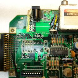
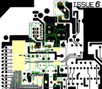
Difference between revisions of "EPower (Magyar)"
From Enterprise Wiki
(Created page with "EPower module (top view) EPower module (bottom view) =Röviden az EPower-ről= Az EPower modul az eredet...") |
(No difference)
|
Revision as of 12:57, 8 December 2022
Contents
Röviden az EPower-ről
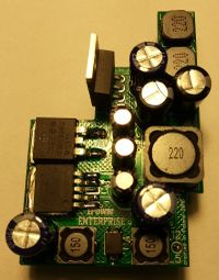
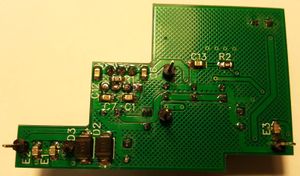
Az EPower modul az eredeti Enterprise tápáramkör kiváltására készült.
Specifikáción
A modul háromféle tápfeszültséget képes előállítani:
- 12 V @ 0.7 A,
- 5 V @ 1.5 A channel A,
- 5 V @ 1.5 A channel B.
Az 5 voltos stabilizátor árama korlátozva van 3.7 A [I = 37125 / R1] (ha szükséges, növelhető 7 A-ig, de ez tönkre teheti a gép áramköreit).
Legnagyobb értékek (a felhasznált alkatrészek miatt):
- 12 V @ 1.0 A,
- 5 V @ 2.3 A csatornánként (egyenként 5A+5B @ 4.5 A).
Ez jóval több mint amire az eredeti áramkör képes (12 V @ 0.15 A és 2x 5 V @ 1 A).
Beszerelés
A modul tervezője minden tőle telhetőt megtett, hogy a modul megbízható és biztonságosan haszálható legyen.A módosításokat mindenki a saját felelőségére végzi el !
Szükséges eszközök
- EPower modul
- csavarhúzó
- forrasztó páka
- ónszippantó
- forrasztóón
- fogók
Az Enterprise alaplapjának előkészítése
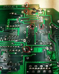
A következő alkatrészeket ki kell forrasztani az alaplapból:
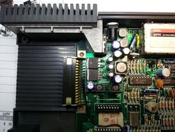
Installing the module
How to make the EPower
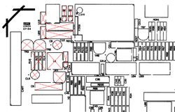
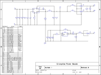
Scheme
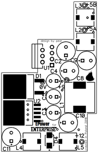
PCB
- Gerber files [EPower.gbr.zip]
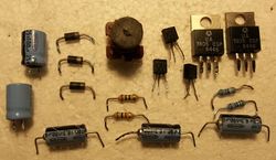
Bill of materials (BOM)
| RefDes | Name | Value |
|---|---|---|
| +9 | TESTPOINT | |
| +12 | TESTPOINT | |
| +5A | TESTPOINT | |
| +5B | TESTPOINT | |
| 0V | TESTPOINT | |
| C1 | CAP_0805 | 10 nF |
| C2 | CAP200RP | 220 µF / 25 V |
| C3 | CAP200RP | 15..22 µF / 25 V |
| C4 | CAP200RP | 15..22 µF / 25 V |
| C5 | CAP200RP | 15..22 µF / 25 V |
| C6 | CAP_0805 | 470 nF |
| C7 | CAP_0805 | 1 nF |
| C8 | CAP200RP | 180..220 µF / 10 V (low ESR) |
| C9 | CAP200RP | 180..220 µF / 10 V (low ESR) |
| C10 | CAP200RP | 220 µF / 25 V (low ESR) |
| C11 | CAP200RP | 220 µF / 10 V |
| C12 | CAP_0805 | 100 nF |
| C13 | CAP_0805 | 330 nF |
| D1 | C3D08060G | 6 A Schottky diode |
| D2 | S1A | 1 A universal diode |
| D3 | S1A | 1 A universal diode |
| D4 | SK110 | 1 A Schottky diode |
| E1 | EMIFIL | MURATA NFM21PC475B1A3D |
| E2 | EMIFIL | MURATA NFM21PC475B1A3D |
| E3 | EMIFIL | MURATA NFM21PC104R1E3D |
| L1 | DE_1207 | 22 µH @ 4.7 A |
| L2 | DE_0704 | 22 µH @ 2.3 A |
| L3 | DE_0704 | 22 µH @ 2.3 A |
| L4 | DE_0704 | 15 µH @ 1.4 A |
| L5 | DE_0704 | 15 µH @ 1.4 A |
| R1 | RES_0805 | 10 kΩ (current output limiter) |
| R2 | RES_0805 | 3 kΩ |
| U1 | LM2679T-5 | |
| U2 | LM2585S-12 |
Links
Thread on the Enterprise Forever forum Enterprise Power module - EPower
Manual in other languages
Hungarian
