EPower
From Enterprise Wiki
Contents
Brief information
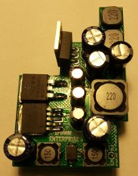
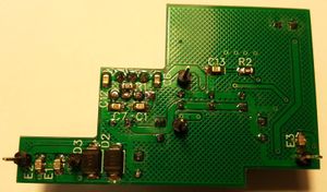
The EPower module replaces the original Enterprise power circuits.
Specification
The module has three power sources:
- 12 V @ 0.7 A,
- 5 V @ 1.5 A channel A,
- 5 V @ 1.5 A channel B.
The current limitation of the 5 V stabilizer is set at 3.7 A [I = 37125 / R1] (the maximum possible current is 7 A, if need, but it could damage the circuity of the computer).
Maximum values (limited by used components) are:
- 12 V @ 1.0 A,
- 5 V @ 2.3 A per channel (both 5A+5B @ 4.5 A).
This is much more than the original power source (12 V @ 0.15 A and 2x 5 V @ 1 A).
How to install
The author has made every effort to make the module as reliable and safe to use as possible. However,
You make any modifications inside of your equipment at your own risk !
What you need
- EPower module
- screwdriver
- soldering iron
- tin extractor
- solder tin
- pliers
Enterprise mainboard preparation
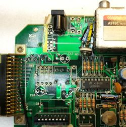
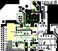
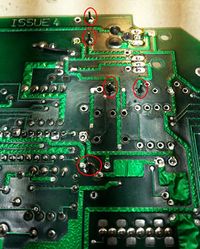
The following components should be desoldered from the motherboard:
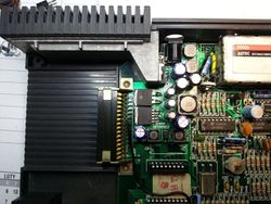
Installing the module
How to make the EPower
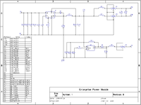
Scheme
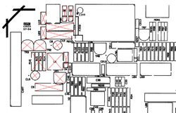
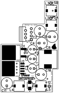
PCB
- Gerber files [EPower.gbr.zip]
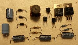
Bill of materials (BOM)
| RefDes | Name | Value |
|---|---|---|
| +9 | TESTPOINT | |
| +12 | TESTPOINT | |
| +5A | TESTPOINT | |
| +5B | TESTPOINT | |
| 0V | TESTPOINT | |
| C1 | CAP_0805 | 10 nF |
| C2 | CAP200RP | 220 µF / 25 V |
| C3 | CAP200RP | 15..22 µF / 25 V |
| C4 | CAP200RP | 15..22 µF / 25 V |
| C5 | CAP200RP | 15..22 µF / 25 V |
| C6 | CAP_0805 | 470 nF |
| C7 | CAP_0805 | 1 nF |
| C8 | CAP200RP | 180..220 µF / 10 V (low ESR) |
| C9 | CAP200RP | 180..220 µF / 10 V (low ESR) |
| C10 | CAP200RP | 220 µF / 25 V (low ESR) |
| C11 | CAP200RP | 220 µF / 10 V |
| C12 | CAP_0805 | 100 nF |
| C13 | CAP_0805 | 330 nF |
| D1 | C3D08060G | 6 A Schottky diode |
| D2 | S1A | 1 A universal diode |
| D3 | S1A | 1 A universal diode |
| D4 | SK110 | 1 A Schottky diode |
| E1 | EMIFIL | MURATA NFM21PC475B1A3D |
| E2 | EMIFIL | MURATA NFM21PC475B1A3D |
| E3 | EMIFIL | MURATA NFM21PC104R1E3D |
| L1 | DE_1207 | 22 µH @ 4.7 A |
| L2 | DE_0704 | 22 µH @ 2.3 A |
| L3 | DE_0704 | 22 µH @ 2.3 A |
| L4 | DE_0704 | 15 µH @ 1.4 A |
| L5 | DE_0704 | 15 µH @ 1.4 A |
| R1 | RES_0805 | 10 kΩ (current output limiter) |
| R2 | RES_0805 | 3 kΩ |
| U1 | LM2679T-5 | |
| U2 | LM2585S-12 |
Links
Thread on the Enterprise Forever forum Enterprise Power module - EPower
